Differential Amplifier
This is the last article in the series of differential op-amp circuits. This is one of the most important operational amplifier circuits and hence it was saved for the last. The speciality of using differential amplifier is that it uses both inverting and non-inverting input terminal to amplify one input signal, while other is fastened to ground Let me remind you that the output is equal to the difference of the input, and as said before it is the special case of operational amplifier where you choose the amplification by choosing the various values of resistance. Let begin the operation by seeing the output voltage from differential amplifier DIFFERENTIAL AMPLIFIER CIRCUIT USING OP-AMP It actually amplifies the variation between two voltage signals with a gain. As you can see, it is very much evident that by varying the resistance value you could amplify the signal to a greater extent. For example, choosing lower value of R1 and higher values of R3 will result in higher amplification of voltage signals. Applications: To amplify the signals Active anti-alias filtering Third – order low pass filter We can get unity gain by using equal values of resistance
The Basic Anti-log Amplifier
The result we get when the base is raised to the power equal to the logarithm of that number is called anti-logarithm of that number. This particular setup can be formed by connecting the transistor or diode as the input element in contrary to logarithmic amplifier. The exponential formula still applies to base emitter PN junction. The circuit for the anti-logarithmic amplifier is as shown below: ANTI-LOGARITHMIC AMPLIFIER USING BJT As in previous case, even diode can be used as the input for anti-logarithmic amplifier, which yields same calculation except for voltage in Vbe. Application: The main application of logarithmic amplifier is signal compression as said in previous article, while we go in to much detail about it, For handling dynamic range of signals which means the ranges of voltages contained in signal, the signal voltage must be constrained by a process called signal compression, for scaling down a signal if linear circuit is used, even the smaller signal will also be constrained by the same level as like the higher amplitude signals hence logarithmic amplifier serve us as, only option for signal compression because it doesn’t eliminate the lower signals as noise.
Logarithmic Amplifier
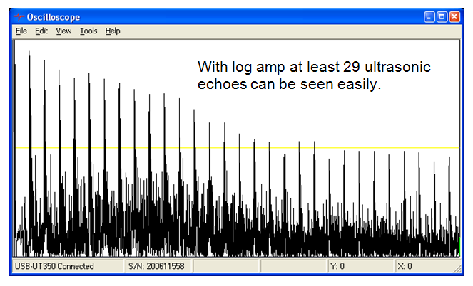
Whenever we are in need of compression of analog input data, we go for logarithmic and anti-logarithmic amplifier. If we need to linearize the transducer that have exponential output and to perform analog multiplication and division, we need to go for logarithmic amplifier We should use a device, which exhibits logarithmic characteristics as a feedback element. It should produce the logarithmic response, which eventually means that the output voltage is a function of the logarithm of input voltage. It can be expressed by Vout = -K ln(Vin) Where ln = natural logarithm to the base e K = constant We need a semi-conductor PN junction. I hope you are all well aware with PN-junction diode and BJT, which provides logarithmic characteristics. Diode always exhibits non-linear characteristics up to forward voltage of 0.7 volts. LOGARITHMIC AMPLIFIER USING DIODE As seen above, if a diode is used as a feedback element of the operational amplifier circuit, the resulting circuit will be logarithmic amplifier. We stick to the basic that inverting input is virtual ground, the output is –Vd when there is a positive input. Since Vd is logarithmic, so is Vout. Since diode’s nonlinear characteristics is reduced to 0.7 volts, the output is also limited to a maximum value of -0.7 volts. Now, will see a logarithmic amplifier using BJT, and all the expression used in logarithmic amplifier using diode is same but instead of Vd, we use V be. And circuit for the same is LOGARITHMIC AMPLIFIER USING BJT Applications Arithmetic operations, Root Mean Square Value detection, Computerized process control, Signal Processing, Compressing and decompressing signals, Log amp is a key component in video and wireless systems
Differentiator using Operational Amplifier
From the series of operational amplifier articles, today will see about differentiating using operational amplifier. Of these differentiating concepts, we use Resistor in the feedback path and capacitor as the input element, fed to the inverting input of the operational amplifier. It leads to the time differentiation of the input signal. The circuit needed for differentiating using op-amp is shown below DIFFERENTIATOR USING OPERATIONAL AMPLIFIER To know how this actually works, we need to feed positive going ramp voltage to the inverting input of the op-amp. In this case the voltage across the capacitor is equal to the Vin at all times. Because the inverting input has virtual ground. We can observe that the Vout is positive going ramp when Vin in negative going ramp and Vout is negative going ramp when Vin is positive going ramp. This is due to the fact that the positive going ramp on the input fed to capacitor and constant current through the feedback resistor which is again fed to the capacitor makes the output voltage go negative ramp, because actually the capacitor is discharging, which eventually ends up with the negative ramp voltage on the Vout of the operational amplifier. Even if it has only limited applications we just formulate using these concepts like Input Output Square Wave Spikes (like ECG graph) Triangular Wave Rectangular Wave Sine Wave Cosine Wave So today we have covered up the differentiator concept of op-amp, will meet up with remaining concept of operational amplifiers in the coming days.
Integrator using Operational Amplifier
So, far till now we have only seen resistor being used in input and feedback, now we are going to use a capacitor in Integrator using operational amplifier, this capacitor forms an RC Circuit with an input resistor. A large value of the resistor is required, because the gain should be limited. The circuit for integrator using operational amplifier is as shown below INTEGRATOR USING OPERATIONAL AMPLIFIER From the concept of virtual ground circuit, the equation for the voltage between input and output, can be derived in terms of current I, from input to output The impedance of the circuit can be written as 1/RC, hence we calculate the output voltage to be From this equation, it is clearly evident that the voltage at the output is the integral of input voltage with reverse polarity and multiplier of 1/RC. With this ability, the integrator allows the analog computer to solve differential equations. As we all know integration is the addition, adding the area under a waveform or curve over a particular period of time. If fixed voltage is applied at the input, the output voltage grows over a period of time, and provides what we call a ramp voltage, This is opposite in polarity to the applied input and multiplied by a factor of 1/RC. You can even use many inputs, with various voltages. Applications of Integrator using Op-Amp: With this circuit, analog computer will be able to solve differential equations Feeding of square wave to the input will result in a triangular wave at the output. If the varying frequency sine wave is fed to the output, the integrator acts as low pass filter
Inverting Summing Amplifier using Operational Amplifier
From the different modes of operational amplifier series, today will see how this inverting summing amplifier works, as many tutorials, videos, books are out there to know about this concept. Very few people provide a satisfactory description about this concept using operational amplifier. INVERTING SUMMING AMPLIFIER USING OP-AMP It may also be termed as widely used operational amplifier circuit. This above circuit shows two input summing amplifier circuit, its output voltage is proportional to the reverse polarity of the summing of input voltages, why is it proportional and not equal, because each voltages are multiplied by a common gain factor. In simple terms, every input adds a voltage to its output multiplied by a separate constant gain multiplier. The output of the inverting summing amplifier using operational amplifier is Vout = -(Rf / R1 Vin1 + Rf / R2 Vin2) And not only two inputs, more and more no of inputs can be added which will eventually add up to the output with its particular constant gain multiplier. This can be more easily understood by the concept of infinite input impedance and virtual ground. The inverting input (-) of the operational amplifier is almost 0 volts and there is no current at the input. And non-inverting input (+) of the operational amplifier is connected to ground. Well, now comes the main part, where do we use this circuit, as I said before, it is the widely used operational amplifier circuit. Let me state it one by one Audio Mixer (Remember all DJ’s move up and down a button which will eventually mix the essentials needed for that song) LED Modulation circuit to keep the operating range linear Bipolar to uni-polar Converter and Digital to Analog Converter and many others.
Inverting Amplifier using Op-Amp

From the different modes of operational amplifier series, this article will stress on the concept of inverting amplifier using operational amplifier Operational Amplifier can be used as inverting amplifer with controlled amount of voltage gain by connecting the op-amp as shown below. INVERTING AMPLIFIER CIRCUIT USING OP-AMP This is a peculiar case in which input signal is applied to the inverting input (-) through a resistor Rin. And output is feedback to the same input through a resistor Rf. As a non-intuitive case non-inverting input (+) is grounded. From the ideal op-amp characteristics, the concept of infinite input impedence is of greater use because infinite input impedence results in zero current at the inverting input. The result of having zero current at the inverting input is we get a no voltage drop between our inverting (-) and non-inverting (+) inputs, because the positive input, which is the non-inverting (+) is grounded, the voltage at the negative input that is the inverting (-) input is zero. This zero voltage at the inverting input terminal is referred as VIRTUAL GROUND. Since, there is no current at the inverting input, the current flowing through our resistor Rf and Rin are equal Iin = If; The voltage across Rin equals Vin because the resistor is connected to the inverting input of the op-amp which may be termed at virtual ground Iin = (Vin/Rin) Rearranging, we get Vout = – Rf Vin Rin From this we conclude the overall gain (A) of the amplifier is A= (-Rf/Ri) It is clearly evident that the output received through the op-amp is of opposite polarity.
Voltage Follower using Op-Amp
From the different modes of operational amplifier series, this article will cover up the concept of Voltage follower using operational amplifier. The voltage follower concept of operational amplifier can be termed as a limited case of non-inverting amplifier where the output voltage received from the output of the operational amplifier is given back to the (-) inverting input by direct connection as shown in the figure VOLTAGE FOLLOWER USING OPERATIONAL AMPLIFIER From the circuit it is very clear that direct connection of the output of operational amplifier to the (-) inverting input of operational amplifier, gives us the voltage gain of 1, which obviously means that there is no gain. As this is a non-inverting amplifier, for a non-inverting amplifier the closed loop voltage gain is 1/B. Since B =1 for a voltage follower, the closed loop voltage gain of the voltage-follower is 1. The significance of this simple voltage follower configuration is Very high input impedance Very low output impedance This kind of circuit may be used in places where you require a buffer amplifier for interfacing low-impedance load with high-impedance sources This voltage follower using op-amp will serve you as an ideal buffer amplifier for interfacing the above condition, I suppose by now you might have understood what I mean by Ideal.
Non-inverting amplifier
From the different modes of op-amp series, This article we are going to study about the non-inverting amplifier application. From the name we can take out two things totally, one is it amplifies the signal, next is it doesn’t change the phase of the input signal the output of the non-inverting amplifier is same as the phase of the input. Always the input signal to be fed is passed through the non-inverting amplifier circuit through the positive input of operational amplifier. And the output from the op-amp is fed back to the negative input of the operational amplifier through the feedback resistor and the signal is grounded through input resistor. V1 = R2/(R2+R1); The difference between the input voltage or source voltage (Vs) to the feedback voltage (V1) is the differential input to the op-amp(Vs – V1). Actually, this differential input is the actual input fed to the non-inverting amplifier. That is amplified by the open loop voltage gain of the op-amp (G). By using this gain, we get a resulting output voltage as Vout = G(Vs – V1). NON INVERTING AMPLIFIER Vout = output voltage G= Open loop voltage gain of the operational amplifier Vs = Source voltage fed to the non-inverting or positive input V1 = feedback voltage from the output of the op-amp Vout = Vs *(1 + (R1/R2); By setting up different values of Resistor you change the amplification level to any extent possible. From this math, it is clear that Higher values of R1 and lower values of R2, will amplify the signal to the significant level. You could use this to amplify signal and to get the same phase of the signal applied at the input. Hope you now know the use of non-inverting amplifier working using operational amplifier.
Operational Amplifier (Op-Amp)
Different modes of Op-Amp Voltage comparator Non-inverting amplifier Inverting amplifier Voltage Follower Inverting summing amplifier Differential Amplifier Differentiator Amplifier Integrator Amplifier Logarithmic Amplifier Anti-Logarithmic Amplifier In this article, will get to know about voltage comparator in detail, and how it could be used practically for specific purposes Practically a Operational –Amplifier has two inputs and one output, two inputs are named as inverting and non-inverting inputs, output is totally based on these inputs, Practically the output of the op-amp is V (output) = 1; if V (non-inverting) > V (inverting) And V (output) = 0; if V (inverting) > V (non-inverting) Where can I use this practically, it is almost used in many analog circuits for converting analog signals to digital signal, well how do I accomplish it. It’s relatively easy Assuming I am getting an analog signal from a sensor, I try to feed it to non-inverting input and let me map it from 0 to 5 volts and on the inverting input of the operational amplifier I try to have another sensor of same type which outputs analog signal and I feed it to inverting input, Assuming the sensors are on the left and right, Now I am doing something for the left sensor to go high, for example an Photo diode, Op-Amp outputs 1, by comparing the right sensor signal output, now with that high signal do something and when you do something to make left sensor go low it automatically outputs the low value, and you can do something for that, and very easily an analog signal is converted to digital signal. From this diagram, you can now that left sensor is fed to (non-inverting) V+ and right sensor is fed to (inverting) V-. Input Output (V+) > (V-) 1 (V-) > (V+) 0 We say greater or lesser than because input fed to operational amplifier is analog signals, in which it’s best for us to compare to get accurate results