Battery
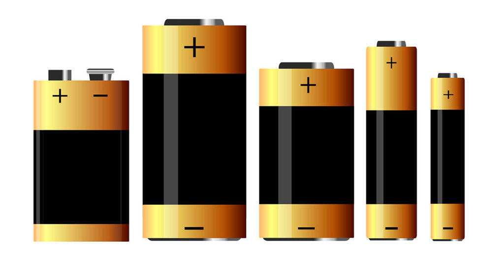
In this section of our tutorial, you will understand about battery capacity, how long will it run, and other parameters. For example if the motor at the no load condition (which means you have not connected to any wheel or any gear to the motor shaft) is consuming 0.2 Amps and you are running the motor using 12 volt 1.3 Ah battery, now the motor will run for [1.3 (Ampere-hour) / 0.2 (Amperes)] will results in 6.5 hours, now theoretically motor will run for 6.5 hours if you run it in no – load condition. But practically as the expert states battery will provide only 70 percent of its full capacity, therefore 1.3 x 0.7 equals 0.91 Ah, then practically it will run for 0.91/0.2 which is 4.55 hours And one more thing to be noted in this section particularly, the amount of amps drawn by a motor would be controlled by itself, even if you feed the motor with high amperage battery, motor will take in the amount of amps it requires leaving the rest. So by this you can understand that a small motor can run even with inverter battery (high amperage battery) without any problem provided the voltage rating is correct.
Direct Current (DC) vs Alternate Current (AC)
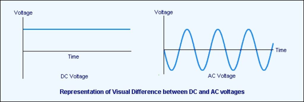
In the line of robotics tutorial, we will see about AC and DC in this section. Almost all electronic components runs on DC, to understand it in simple terms, first let us know about how electrons flow in DC and AC using some small examples. Assuming, we have battery and a motor in which motor is connected directly to the battery after which the motor runs. Now if you watch closely the electron flow, it is very well known that electrons from positive terminal of the battery will flow to the motor and and ends up in the negative terminal of the battery, which is one way mostly. Now to understand AC, assuming we have connected a bulb to the wall socket. Here let us see how electrons flow. At the first phase, electrons will flow in clock wise direction in the circuit as indicated in the video, and in the second phase, the electrons will flow in the counter clockwise direction, since it has a nature of altering its electron flow, which we call it as Alternating Current. Reasons for having AC supply in household are: 1. Transmission loss is less in AC compared with DC 2. Safety for human beings 3. Safety for devices
How IC L293D runs a motor?
IC L293D is a 16 pin motor-driver IC that replicates the basic concept of a transistor. It is built-in with two H-bridge driver circuits to drive two DC motors simultaneously. One of the greatest advantages is that it can run the motor in both directions: clockwise and anti-clockwise. L293D Pin-Out: The L293D is designed to provide bidirectional current up to 600 mA, and the voltages from 4.5 v to 36 v. In this L293D, there are two enable pins (pin 1 & pin 9) for activating the IC. When the ENABLE pin 1 is high, the left part of IC will work, if it is low it will not work. Same condition applies to ENABLE pin 9 in which the right part of IC will work. And there are 4 input pins and 4 output pins in this IC. The 4 input pins are 2, 7, 10 & 15. Pin 2 & 7 are in the left hand side and pin 10 & 15 are in the right hand side. Left side pins will regulate the motor connected across the left motor, and the right side pins will regulate the motor connected across the right motor. And the 4 output pins are 3, 6, 11 & 14, these output pins are connected to the motors respectively. The pins 4, 5, 12 & 13 are ground pins. The pin 8 will go to Vcc, which will be supplied to the motor, and pin 16 will go to Vss that is supplied to the IC. H-Bridge: H-bridge is an electronic circuit. It allows a voltage when the load is applied across on the either direction of a circuit. H-Bridge Driver Circuit Working of an H-bridge circuit: The term ‘H-bridge’ is derived from the schematic of four switches (S1, S2, S3, & S4) connected with a DC motor. The motor will run only on the basis of inputs provided across the four switches. Check the below tabular column to know how H-bridge enables a motor? Two states to run a motor Final Thoughts: IC L293D is a cost-efficient electronic device, which is quite often used in robotic applications to run two DC motors on both forward and reverse directions. Other motor-driver IC’s similar to L293D are L298 & ULN2003. IC L298 is quite costly, while IC ULN2003 does not have a H-bridge circuit to run the motor on any directions. Overall, IC L293D is the best motor-driver IC for small applications. Download L293D Datasheet
Working of Light Dependent Resistor (LDR)
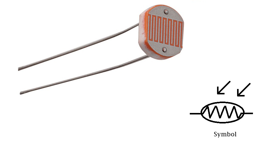
LDR (Light Dependent Resistor) is one of the most cheapest light sensor and most commonly used in light sensor circuits in open area (e.g. auto switching street lamps). It is made of semiconductor materials and the semiconductor used in this systems are cadmium sulphide, lead sulphide, germanium, silicon and gallium arsenide. The main role of LDR is, when the light increases resistance decreases and when the light decreases resistance increases and the operating temperature is min = -60°c, max = 75°c and the circuit symbol of LDR is shown below : Symbol of LDR You may raise a question, when LDR detects light or dark, how long it takes the resistor to make a change? Resistance Rise Time is 2.8 ms for 1000 LUX Resistance Rise Time is 18 ms for 10 LUX Resistance Fall Time is 48 ms for 1000 LUX Resistance Fall Time is 120 ms for 10 LUX At complete darkness the resistance value is 1MΩ. According to the above description it is clear that, the resistance fall and rise time depends upon the intensity of light illumination and in the below table you can view the illumination of light for various source. Sensitivity of LDR is the relationship between the light falling on the component (LDR) and the output of the resistance value (refer the below characteristic graph of LDR). Solar Tracking Robot will be the best example to explore the working of LDR.
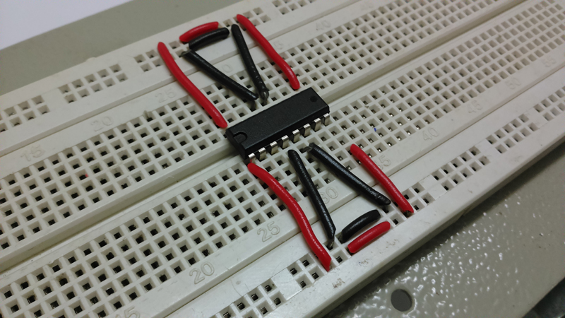
Breadboard and it’s Uses
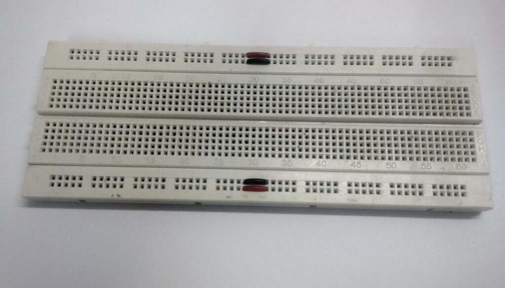
Breadboard is mainly used to develop temporary electronic circuits for trial and testing purposes. One of its greatest advantage is that it doesn’t require soldering for connecting the electronic components. All you have to do is to just push the leads of the electronic components straight into the holes. Breadboard has many tiny holes separated by 0.1”. At the top of the breadboard you can find two row’s, each row is horizontally connected with each other, similarly at the bottom of the bread board you can find two row’s, each row is horizontally connected with each other. In mid portion of a breadboard, you could find two rows separated by a small gap. These holes are connected vertically. Each vertical connection holds five holes which are connected with each others (refer the below breadboard). And while we connect an IC in a breadboard, we should connect in the manner which is indicated above. Breadboard Tips: Always use the horizontally-connected row lines for power supply and for ground connection. Connect a small strip of wire between 5th & 6th column in the top and bottom rows (as shown in the above picture). Always use black wires for ground and red wires for power supply, so it makes good sense to your circuit design. Always keep hookup wires flat on the board. Always locate hookup wires around the chip and not over the chip. Finally trim the legs of components like resistor, capacitor, transistor and LED’s, so it fixes correctly to the board firmly and by doing this you can avoid the short circuit issues.
How IC HT12D works?
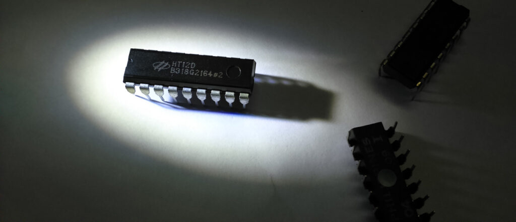
ASK RF Receiver receives the data transmitted from ASK RF Transmitter. The input code set to address pins A0-A7 at HT12E should match with the address pins of HT12D. If it is valid, the LED connected to the below circuit (fig 2) will glow and then transmission of data get starts. The positive and negative of the power supply is fed into HT12D via VDD and VSS respectively. Fig. 1 HT12D is a 212 series decoder, most commonly used in remote control applications. By using the HT12E encoder and HT12D decoder, we can transmit 12 bits of parallel data serially. HT12D converts serial data to its input to 12 bit parallel data. These 12 bit parallel data is divided in to 8 address bits and 4 data bits. For the internal oscillator in HT12D an external resistance is connected in between OSC1 and OSC2 finally it forms an RC oscillator. The serial data input is given to DIN from the output of RF receiver. Initially, HT12D decoder will be in standby mode. As a result, oscillator is disabled and when a high input is given to DIN pin activates the oscillator (you can also understand the overall operation of HT12D decoder by following the flow chart).
How IC HT12E Works?
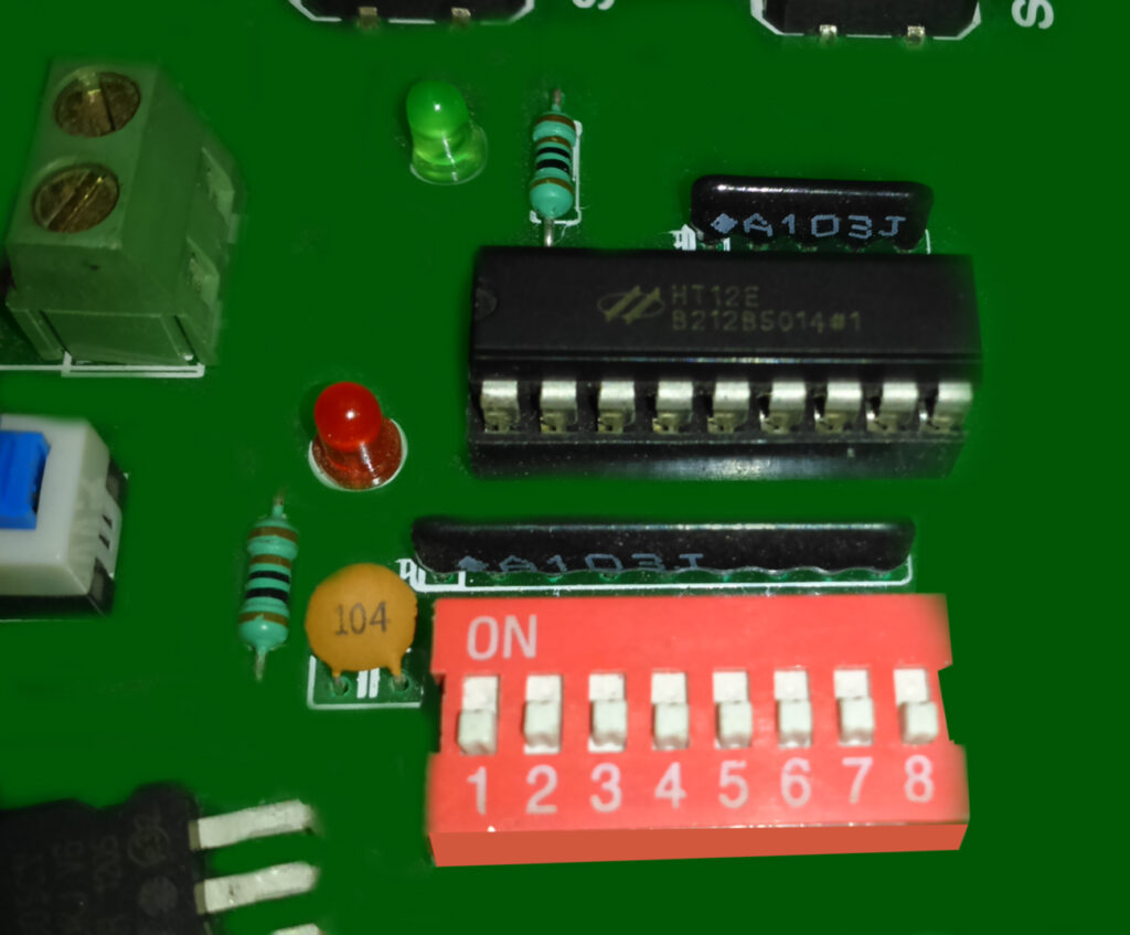
HT12E is a 212 series encoder most commonly used in remote control applications. It contains totally 12 input pins in which 4 pins are used for data/address bits (AD8-AD11) and 8 pins for address bits (A0-A7) for safe transmission of data for security purposes. The unique function of HT12E is to convert 12 bit parallel data inputs into serial data output (pin17) and then it is modulated and transmitted using the RF transmitter module. The power consumption is very low and the standby current is 0.1µA at5V. HT12E has a transmission enable pin which is active low. When a trigger signal is received by TE (pin14), the addresses/data are transmitted together through an RF transmitter module. HT12E is a 4 word transmission cycle enables. This cycle is repeated again and again till TE is kept low. When TE returns to high, the encoder has completed its last cycle and then stops. (You can also refer the following flow chart for clear view on transmission enable, which is active low). The positive and negative of the power supply is fed into HT12E via VDD and VSS respectively. For the internal oscillator, an external resistance is connected in between OSC1 and OSC2 finally it forms an RC oscillator. You may raise a question on how to choose the resistance value? Well, for the selection of resistance refer the below graph between the frequency of oscillation and the power supply. How the Digital Serial Data gets transmitted from TRANSMITTER to the RECEIVER? Here we go, it is very simple to transmit a serial digital data through RF transmission and the technique used here is Amplitude Shift Keying. In amplitude shift keying the digital serial data are represented in amplitude of the carrier wave. The serial output DOUT is given to ASK transmission and one important thing is the transmitter address should match the receiver address. It helps the receiver to receive the RF signal and then decode it.
How IC CM8870 works as DTMF Receiver?
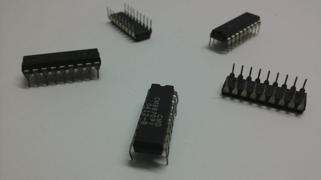
CM8870 can also be termed as DTMF receiver and it is integrated with both band split filter and decoder function into a single IC 18-pin. The power consumption of the IC is 35mW maximum. BANDSPLIT FILTER – as we have already seen that a single tone is superimposed with two frequencies, one is low and the other is high frequency, to split this two frequency into high group frequency and low group frequency and then it is decoded. DECODING – In CM8870, digital counting techniques are used to decode all 16 DTMF tone pairs into a 4 bit code. For example: if you press a key 3, the corresponding low and high frequency is 697Hz and 1477Hz (refer the DTMF frequency table) these two frequencies superimposed to produce a single tone and this tone code is sent through the microphone and the signal is received by a DTMF receiver (CM8870), then the superimposed frequencies are separated by bandpass filter, then decoded using digital counting techniques and the digital output is 1100 (Q1, Q2, Q3, Q4) pin (11, 12, 13, 14). So it is very simple to interface. Feeling Interested! Learn to interface a mobile phone and the robot.
Properties of Sensors used in Robotics
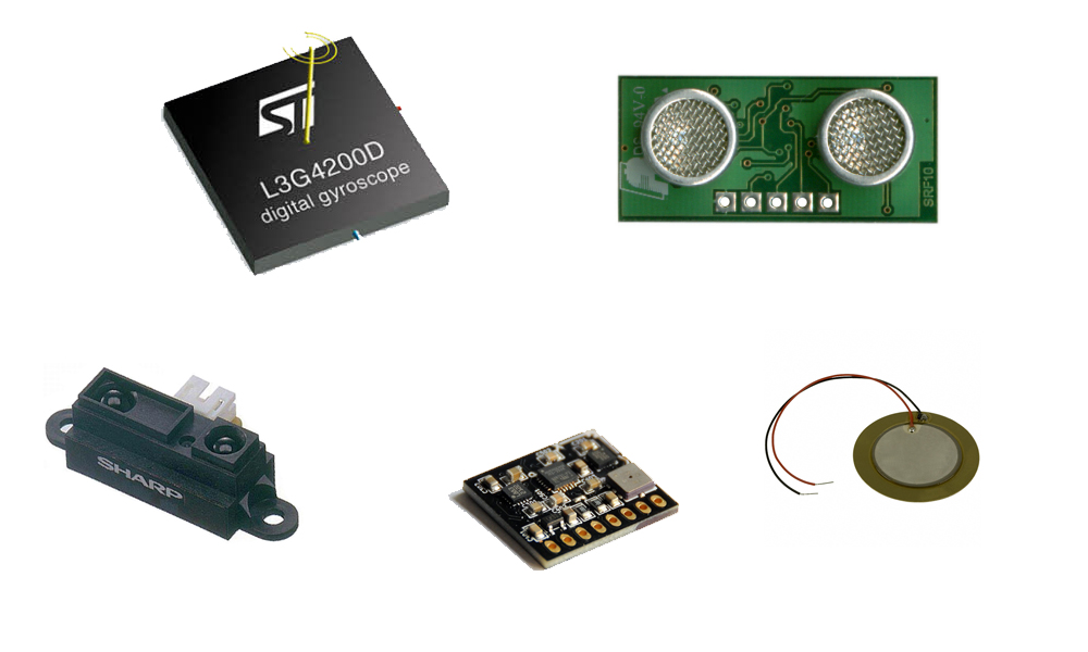
1.Field of view and Range: Often called FOV (Field of View) is the most important aspect while selecting a sensor. First, to what distance does it cover? Field of View and Range may be measured in metres, degrees in vertical and horizontal. This may be understood by knowing the concept of photography because those people use different types of lenses for different size, place, location, and atmospheric visibility. Hence while selecting sensor, it is best for us to know its field of view, range and direct application. 2.Accuracy, Repeatability and Resolution: Accuracy always refer to true value (i.e. actual value). Repeatability may be defined as the measurement from the sensor, which repeats itself for the same physical conditions. 3. Responsiveness in required application: There are some sensor which behaves very poor under certain conditions, so before selecting any kind of sensor for particular application, we have to check whether the sensor works fine under particular condition. For example, some sensor work at highly illuminated place but our application will require sensor to work only in that particular area. Hence choosing sensor which works in targeted area will be of utmost importance. 4. Size: This is a common attribute of a sensor, which every engineer normally looks out for. Because, the circuit casing size will almost be ready by the time we look out for sensor and particular size. 5. Power Consumption: As far as robotics or any other application, almost about 90% of application runs with batteries. So, will have to look at the power consumption of the sensor being used. In case, if it consumes more it will drastically reduces run time of our robot. 6. Ambience: Get to know the temperature it can withstand, assuming you are using sensor in some industrial area where the temperature is high integrated with noise pollution, some sensors might not function in such cases. So, its better for us to look for the maximum temperature it can withstand. httpvh://www.youtube.com/watch?v=cquvA_IpEsA
Processing IDE
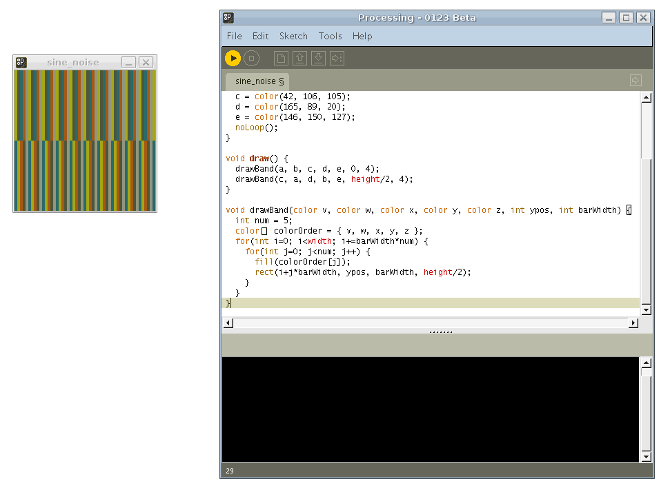
Processing is an Integrated Development Environment built in 2001 by Casey Reas and Benjamin Fry. These guys are from MIT (Media Labs), Aesthetics and Computational Group. They were working on something so that something could get non-programmers to start a program. For your information, Arduino language is based on Processing IDE, and is very much similar to the Arduino IDE. Processing IDE is based on Java, whereas Arduino IDE is based on C/C++. Fine, where do we use Processing, as said earlier, it was created with a motive of bringing non-programmers to programming. This IDE could be visually interactive, you could get a 2 dimensional or 3 dimensional output from your program which is really interesting once into it. More than anything, it is an open-source software. I suppose the way the MIT Media Lab is going, we could sense an exemplary world where people would be free of all physical activities and automatic systems like robotics would be ruling us (virtually). Download processing IDE, then its way to go, will you able to draw all the things on the computer which you can draw with paper and pencil. Fine, Paint might be the very good answer to this, in other case, how could you draw pictures using programs. Do you think it’s hard enough, not it’s not the case, you could use processing to do this very much easily. Do you know Samsung’s sixth sense technology, where you could switch the channel using fingers by sitting in front of it without any contact, fine how do they do that, The answer is simple they use some kind of software similar to processing, I am not sure what they used, but after knowing Processing software you could be able to design a Samsung monitor of the same sixth sense technology. Well, then go to the download page in processing, start to download and enjoy working with processing, Start to process the processing.